Encoder in Digital Electronics
In this article we will not talk about what encoding we specify for any text, rather we will focus on “how” the encoding process works. Let’s delve deep into it right away!
What is Encoder in Digital Electronics?
In an Encoder, typically we have ‘n’ input lines and ‘m’ output lines. What are lines? Wires! Now obviously, since we’re trying to optimize storage and reduce wires, the encoder must be somehow reducing the input, making the ‘m’ output lines lesser than ‘n’ input lines. The relationship between n and m here, is – maximum 2n input lines, with n output lines. The job of the encoder would be to convert the 2n inputs to n-bit code.
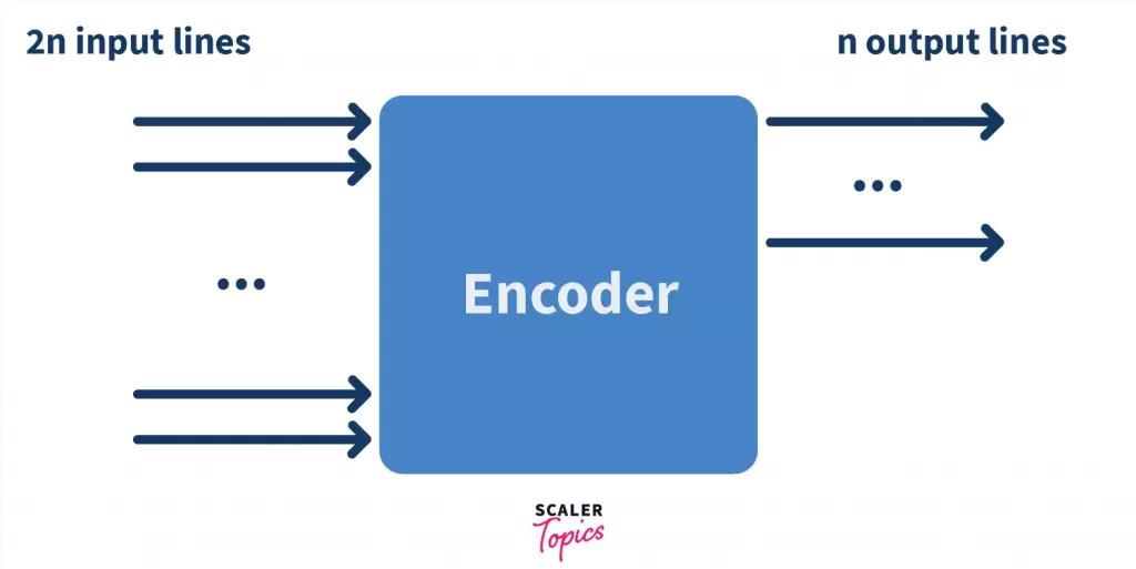
So for example, if we have 4 input lines, the number of output lines would be 2, because 22 = 4. Similarly, if there are 8 input lines, there would be 3 output lines because 23 = 8. Each type of encoder is used according to the number of inputs to be given or the output required.
Types of Encoders in Digital Electronics
4 to 2 Encoder
Using 2 fingers, you can make 4 states (22 = 4). Calling 0 as finger closed and 1 as finger open, states would look like 00(both closed), 01(1st closed, 2nd open), 10(1st open and 2nd closed), 11(both open). This is the exact analogy used in the diagram below. Consider l0, l1, l2, l3 are the 4 values on the input lines that you want to represent uniquely and A1 and A2 are the two fingers that you will use to represent the same data. Here, l0, l1, l2, l3 can be restored from A1,A2.
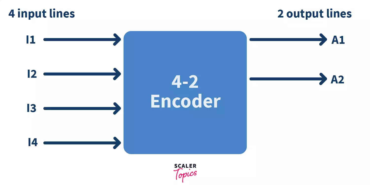
Take a look at the input output table which we call a truth table below, showing all the combinations and their outputs.
| INPUT | OUTPUT | ||||
|---|---|---|---|---|---|
| l3 | l2 | l1 | l0 | A1 | A0 |
| 0 | 0 | 0 | 1 | 0 | 0 |
| 0 | 0 | 1 | 0 | 0 | 1 |
| 0 | 1 | 0 | 0 | 1 | 0 |
| 1 | 0 | 0 | 0 | 1 | 1 |
As we can see, we have successfully ‘encoded’ 4 combinations (0000, 0001, 0010, 0100, 1000) of 4 bit inputs to half its size (00, 01, 10, 11). Now to implement this in hardware, we would need something we call in digital electronics as ‘logic gates’.
Writing the logical expressions for each of the output variables in the SOP form (SOP stands for Sum Of Products, wherein we write an equation for the variable as a summation of the terms that are ‘1’)
A1 = I3 + I2 A0 = I3 + I1
Now one thing to notice here is that in none of the equations, do we have I0, which means that whether I0 is 0 or 1, the output is the same 0 0, hence we do not utilize it in the encoder.
The hardware implementation of the above output lines using logic gates can be done using 2 OR gates.
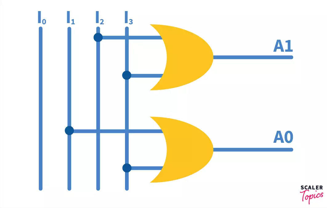
To prove that the above circuit diagram is correct, let’s take an input from the truth table.
I0, I1, I2, I3 = 0, 1, 0, 0 respectively.
Octal to Binary Encoder (8 to 3 Encoder)
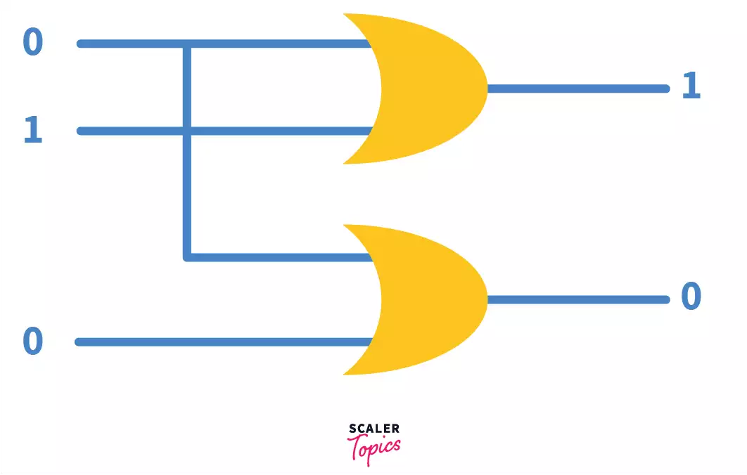
The number of inputs here are 8, namely – I0, I1, I2, I3, I4, I5, I6, and I7. The output lines are 3 – A0, A1, A2. Every input line represents an octal digit, and the output lines represent the binary code output.
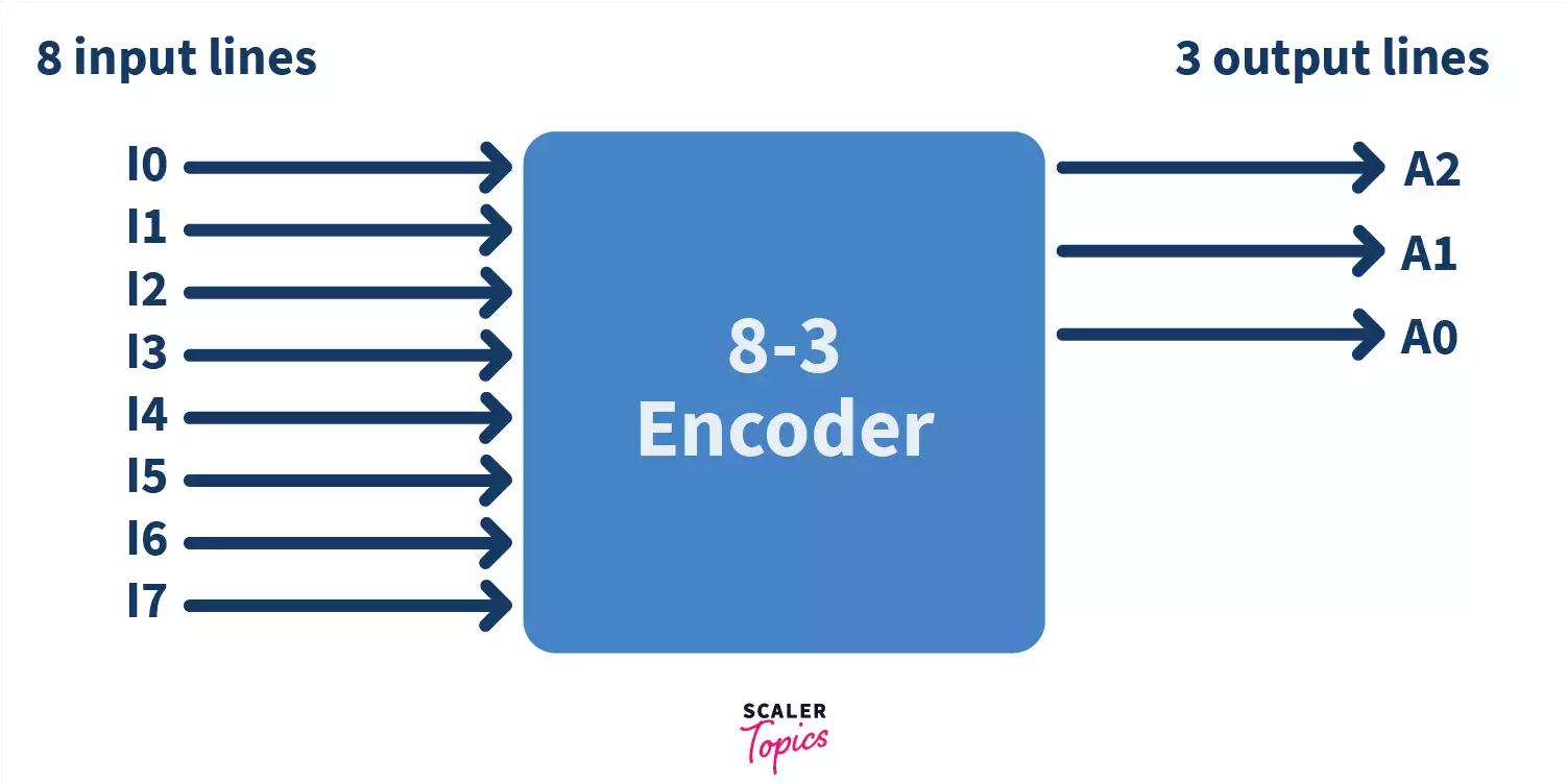
Look carefully, only 1 input line has an ‘active High’ input, i.e. the value ‘1’.
| INPUT | OUTPUT | |||||||||
|---|---|---|---|---|---|---|---|---|---|---|
| I7 | I6 | I5 | I4 | I3 | I2 | I1 | I0 | A2 | A1 | A0 |
| 0 | 0 | 0 | 0 | 0 | 0 | 0 | 1 | 0 | 0 | 0 |
| 0 | 0 | 0 | 0 | 0 | 0 | 1 | 0 | 0 | 0 | 1 |
| 0 | 0 | 0 | 0 | 0 | 1 | 0 | 0 | 0 | 1 | 0 |
| 0 | 0 | 0 | 0 | 1 | 0 | 0 | 0 | 0 | 1 | 1 |
| 0 | 0 | 0 | 1 | 0 | 0 | 0 | 0 | 1 | 0 | 0 |
| 0 | 0 | 1 | 0 | 0 | 0 | 0 | 0 | 1 | 0 | 1 |
| 0 | 1 | 0 | 0 | 0 | 0 | 0 | 0 | 1 | 1 | 0 |
| 1 | 0 | 0 | 0 | 0 | 0 | 0 | 0 | 1 | 1 | 1 |
The logical expressions for the output lines from the table above calculated using boolean algebra:
A2 = I7 + I6 + I5 + I4 A1 = I7 + I6 + I3 + I2 A0 = I7 + I5 + I3 + I1
Did you notice? The value in the input line I0 doesn’t affect any of the output lines, just like the previous 4 to 2 encoder?
These equations can be implemented with 3 OR gates in hardware as given below.
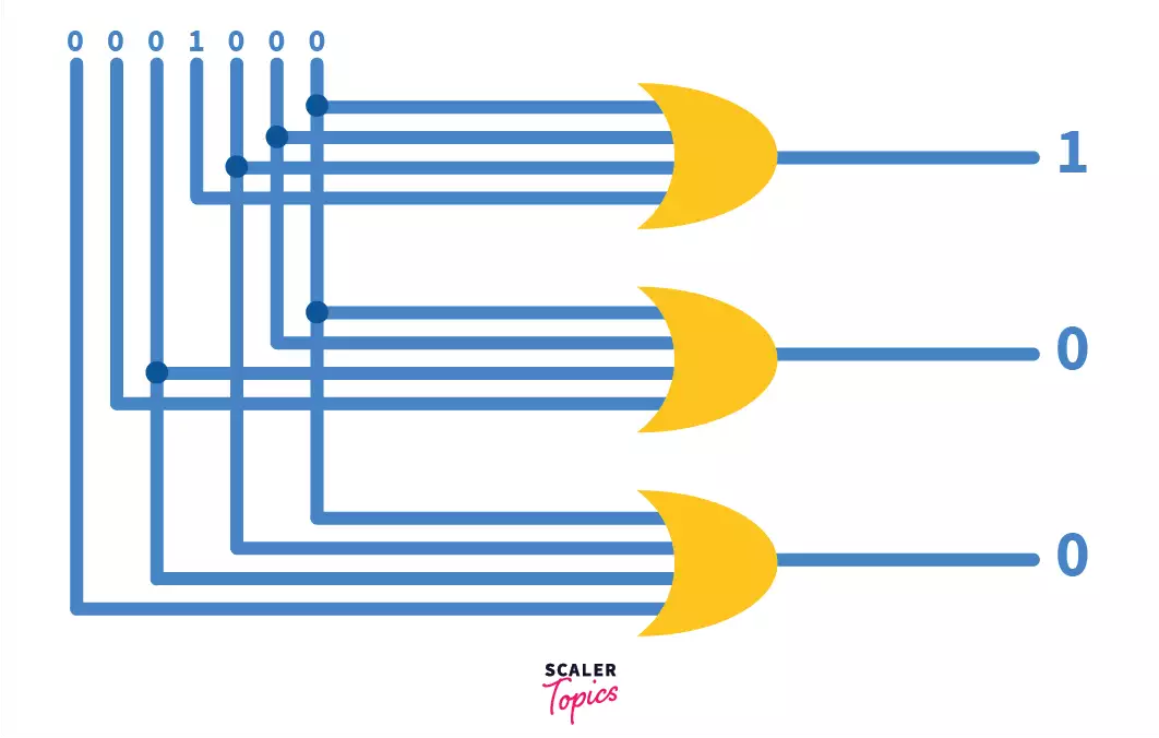
Decimal to BCD Encoder
The typical decimal to binary encoder consists of 10 input lines and 4 output lines. Why? To explain this in simple terms, we know that we have 10 input lines implemented in the hardware. How do we decide the number of output lines? As written above, for a “maximum” of 2n input lines we can have n output lines.
For our input, 10, the closest high power of 2 is 16.
2n = 16, hence n = 4 = number of output lines.
More mathematically, to represent n output lines we require at least ceil(log2(n)) lines.
For this reason log2(10) = ceil(3.32) = 4 lines.
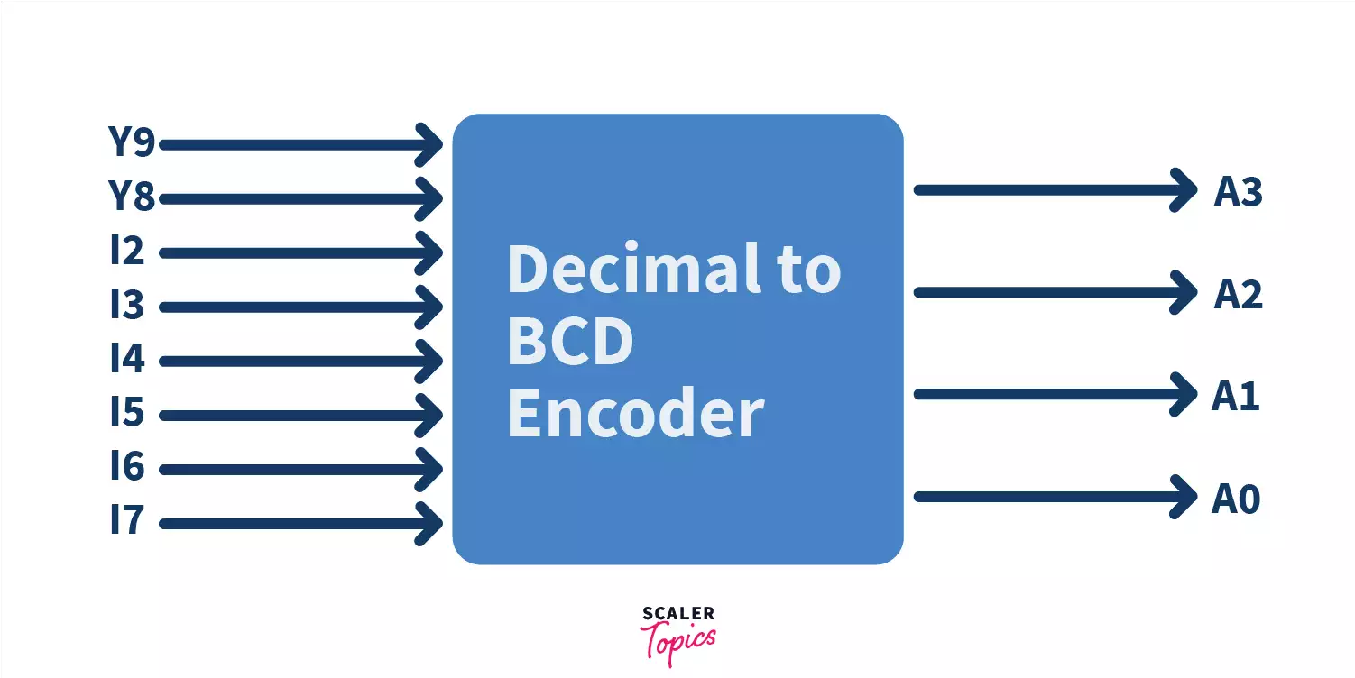
A3 = I9 + I8 A2 = I7 + I6 + I5 +I4 A1 = I7 + I6 + I3 +I2 A0 = I9 + I7 +I5 +I3 + I1
Using these equations, we can create the following logic circuit for the encoder.
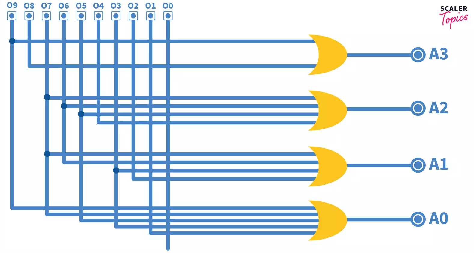
The truth table, circuit diagram, everything seems fine. But we have 4 output lines, which should generate 24 = 16 outputs, and we use only 10? What happened to the other 6? Well, in normal encoders such as these, only one input line can have the value ‘1’ or be ‘active high’ at a point of time. And since we have only 10 input lines, only 10 outputs are possible.
Priority Encoder
It has 4 inputs, and 2 outputs. It could happen that more than one input bit is active high, and this main problem, of the count of active High bits being more than one, can be solved by giving priority to MSB bits. MSB is short for Most Significant Bit and refers to the left most bit. The encoder will start checking for a high input from the MSB end, and as soon as it finds one, it gives output according to that bit, ignoring any other active High inputs present in the input lines. So since it ignores any other high bits, we give them “don’t care” values in the truth table, which means that we don’t care whether their values are 0 or 1, because they don’t affect the output. These are denoted by “X”.
Truth table:
| INPUT | OUTPUT | |||||
|---|---|---|---|---|---|---|
| I3 | I2 | I1 | I0 | A1 | A0 | V |
| 0 | 0 | 0 | 0 | 0 | 0 | 0 |
| 0 | 0 | 0 | 1 | 0 | 0 | 1 |
| 0 | 0 | 1 | x | 0 | 1 | 1 |
| 0 | 1 | x | x | 1 | 0 | 1 |
| 1 | x | x | x | 1 | 1 | 1 |
To derive the logical expressions for the three output variables, we would need to use a K-Map since we have some “don’t care” values as well.
Essentially, the idea behind solving a K-map, is that we need to club together values that have value either 1, or X (with preference given to 1) in groups of 2, 4, 8, and so on on the grid. Upon clubbing the values, we can write the logical expressions of the variables using the values mapped to them in the table.
Applications of Encoders in Digital Electronics
- They can be utilized to convert decimal numbers to binary to perform binary functions on them such as addition, multiplication, subtraction, division etc.
- Priority encoders can be used to detect interrupts in microprocessor applications.
- Priority encoders can be utilized to decrease the quantity of wires required in specific circuits or applications that have different data sources. For instance, suppose a microcomputer needs to read the 104 keys of a standard QWERTY console where just one key would be pressed either “HIGH” or “LOW” at any one time.
Advantages of Using Encoders
- Encoders offer exceptional precision and dependability in measuring position, speed, and rotation.
- Encoders provide non-contact sensing, eliminating the need for physical contact with the measured object.
- Encoders provide digital output signals, making them easy to interface with digital control systems.
- Encoders can provide high-resolution measurements, enabling precise control of motion and position.
- Encoders are versatile and can be used in a wide range of applications, including motor control, robotics, CNC machines, automation systems, and measurement devices.
Disadvantages of Using Encoders
- Encoders can be relatively expensive compared to other sensors, especially high-precision encoders.
- Encoders can be sensitive to environmental factors such as dust, dirt, and moisture.
- Some encoders have limited speed ranges and may not be suitable for applications with high-speed motion requirements.
- Magnetic encoders can be affected by magnetic fields, which may introduce errors in measurements.
Conclusion
- Encoders are combinational circuits implemented with the help of logic gates.
- The main idea behind using encoders is to save space occupied by data and reduce the number of wires required to implement circuits.
- Encoders have maximum 2n input lines and n output lines.
- Types of Encoders discussed :
- 4 : 2
- 8 : 3 (octal to binary)
- Decimal to BCD
- Priority Encoder
- Priority encoder solves the problem of ambiguity when all inputs are low, and also the main problem of more than one active High inputs in encoders
