Manchester Encoding
Overview
Manchester code, commonly known as phase encoding, is a line code used in communications and data storage in which each data bit is encoded either high then low, or low then high for an equal period of time. The signal is self-clocking and has no DC component. As a result, galvanically isolating electrical connections using the Manchester code is simple. Before the introduction of 6250 bpi cassettes, which used the more effective group-coded recording, Manchester code was frequently used for magnetic recording on 1600 bpi computer tapes. Manchester code is still used in consumer IR protocols, RFID, and near-field communication. It was first utilized in early Ethernet physical layer specifications.
What is Manchester Encoding?
The physical layer of the Open System Interconnection [OSI] uses Manchester encoding, a synchronous clock encoding technique, to encode the clock and data of a synchronous bit stream. In order to guarantee data security and transmission speed, many encoding techniques are used. A type of digital encoding is Manchester encoding. It differs from other digital encoding techniques in that each data bit length is predetermined by default. The direction of the transition determines the bit state. Different systems display bit status in a variety of ways, but most employ 1 bit for low to high transitions and 0 bit for high to low transitions.
In Manchester, a bit's duration is split in half. During the first half, the voltage stays constant at one level before switching to another level. Synchronization is provided by the transition in the middle of the bit. Differential On the other hand, Manchester blends the concepts of RZ and NRZ-I. The bit values are decided at the beginning of the bit, but there is usually a transition in the middle of the bit. If the next bit is zero, a transition occurs. There is none if the next bit is a 1. The data controls the phase of a square wave carrier whose frequency equals the data rate in Manchester coding, a specific example of binary phase-shift keying (BPSK). Manchester code guarantees regular line voltage changes that are inversely proportional to the clock rate, which aids in clock recovery.
Example of Manchester Encoding
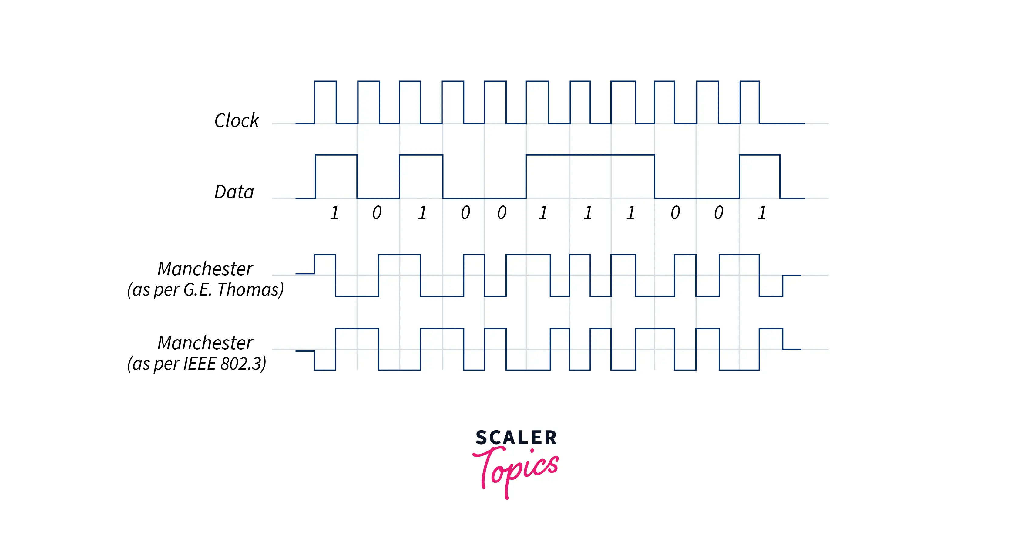
A logic zero is signaled by a transition from 1 to 0 in the middle of the bit in Manchester encoding (as specified by IEEE 802.3 standards for 10 Mbps), and a logic one is indicated by a transition from 0 to 1 in the same location. There is always a transition in the signal, even though it doesn't always happen at the bit boundaries (the line separating one bit from another).
Be aware that occasionally the encoding will be inverted, with 0 being displayed as a transition from 0 to 1. For many years, the two definitions have coexisted. The electrical signal created by inverting line drivers, which are used by many physical layers to translate binary digits into electrical signals, is exactly the opposite of what the encoder would output. This inversion ambiguity is not present in differential physical layer transmission, such as 10BT.
Encoding and Decoding
Manchester code always has a transition in the middle of each bit period, and it might also have one at the beginning, depending on the information being communicated. The data is indicated by the direction of the mid-bit transition. Period boundary transitions do not provide information. They are only there to get the signal into the right state so that the mid-bit transition may happen. A Manchester-encoded signal is converted from one convention to another if it is inverted during communication. By employing differential Manchester encoding, this ambiguity can be resolved.
Decoding
Because there are assured transitions, the signal can be self-clocking and the receiver can align appropriately. If the receiver is out of alignment by half a bit period, it will be able to tell because there won't always be a transition at the beginning of each bit period. The cost of these advantages is an increase in bandwidth usage compared to the more straightforward NRZ coding systems.
Encoding
The following encoding standards apply: Each bit is sent in a predetermined amount of time (the "period"). According to G. E. Thomas' convention, a 0 is represented by a low-to-high transition, whereas a 1 is represented by a high-to-low transition (the IEEE 802.3 convention operates in the opposite manner). The transitions that denote 0 or 1 take place in the middle of a period.
Transitions at the beginning of a period are unnecessary and represent no data.
Non-return-to-zero [NRZ]
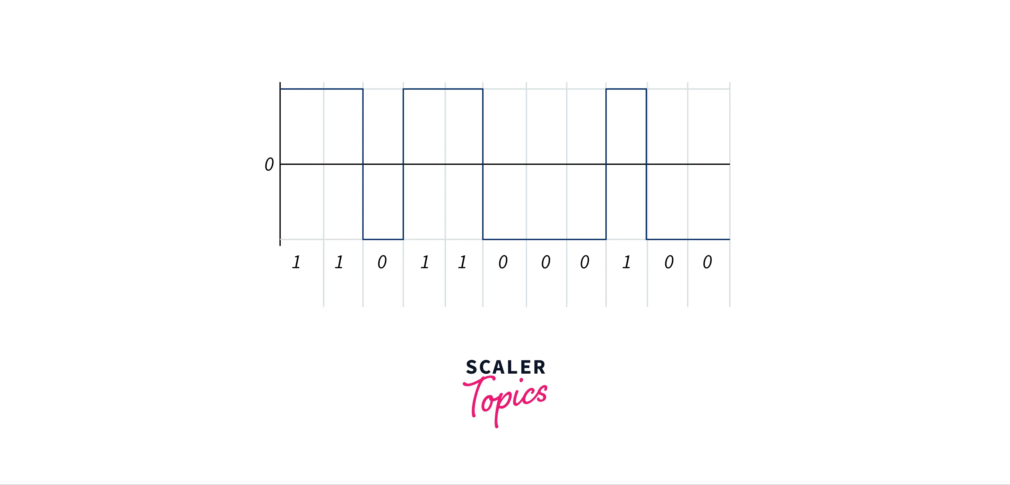
In communications, a non-return-to-zero (NRZ) line code is a binary code in which ones are represented by one major condition, typically a positive voltage, and zeros are represented by another significant condition, typically a negative voltage, with no other neutral or rest state. The NRZ code requires only half the baseband bandwidth needed by the Manchester code for a given data signaling rate, or bit rate (the passband bandwidth is the same). Compared to a return-to-zero (RZ) code, which also has a rest state in addition to the criteria for ones and zeros, NRZ pulses have more energy. The absence of a neutral state necessitates other procedures for bit synchronization when a separate clock signal is not provided when utilized to represent data in an asynchronous communication system. A run-length-limited restriction and a parallel synchronisation signal are two examples of additional synchronisation methods that must be utilised because NRZ is not naturally a self-clocking signal in order to prevent bit slips.
Unipolar Non-return-to-zero Level
A DC bias on the transmission line, which is often positive, symbolizes "one," while a line with no bias, such as one that is grounded or at 0 volts, is symbolized by the number "zero." It also goes by the name "on-off keying" because of this. A "one" in clock language moves to or stays at a biassed level on the trailing clock edge of the previous bit, whereas a "zero" transitions to or stays at no bias on the same edge. Although this is not specific to the unipolar situation, one drawback of unipolar NRZ is that it permits extended series without change, which makes synchronisation challenging. Avoiding sending bytes without transitions is one way. The presence of a transmitted DC level and the fact that the power spectrum of the transmitted signal does not approach zero at zero frequency are more serious problems specific to unipolar NRZ. This causes two serious issues: first, the transmitted DC power results in higher power losses than other encodings, and second, the transmission line must be DC-coupled due to the presence of a DC signal component.
Bipolar Non-return-to-zero Level
One physical level (often a positive voltage) is used to symbolise "one," whereas another level is used to represent "zero" (usually a negative voltage). Bipolar NRZ-level voltage "swings" from positive to negative on the trailing edge of the preceding bit clock cycle in clock language.
This may be seen in RS-232, where "one" is defined as 12 to 5 volts and "zero" as 5 to 12 volts.
Non-return-to-zero Inverted
Bryon E. Phelps (IBM) created non-return-to-zero, inverted (NRZI), sometimes referred to as non-return to zero IBM, inhibit code, or IBM code, in 1956. This technique converts binary signals into physical signals that can be transmitted through a transmission media. The presence or absence of a transition at a clock boundary allows the two-level NRZI signal to discriminate between different data bits. A method for inducing a transition at appropriate intervals is typically used in addition to NRZI since it can be challenging for a receiver to reliably tally a long string of no-transition bits. While HDLC and USB use bit stuffing, which inserts an additional 0 bits (forcing a transition) after 5 or 6 (respectively) consecutive 1 bits, magnetic disc, and tape storage devices typically use fixed-rate RLL coding. While bit stuffing is effective, it causes a fluctuating data rate since sending a lengthy string of 1 bits takes a little longer than sending a lengthy string of 0 bits.
Characteristics of Manchester Encoding
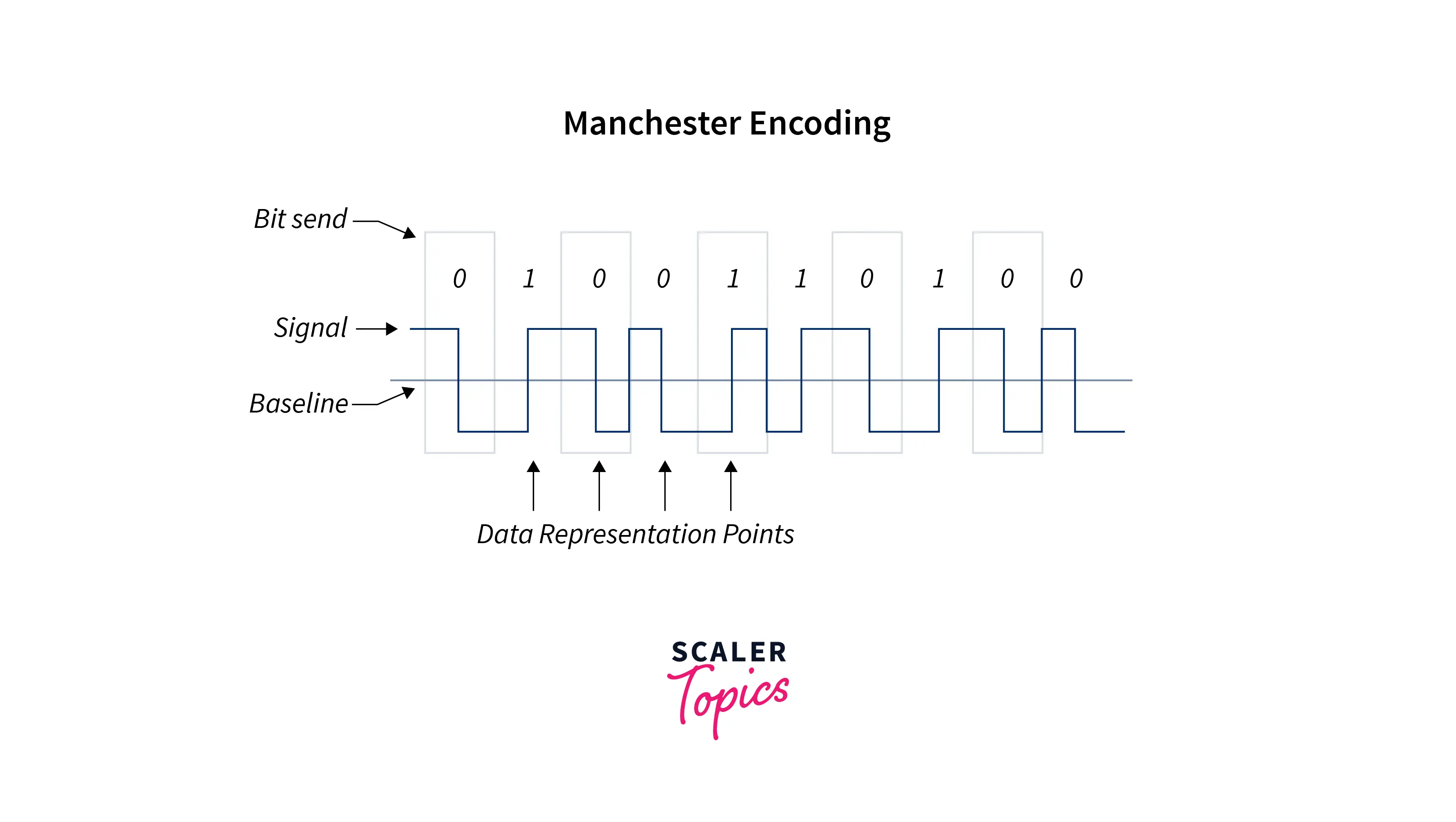
- A 0 to 1 transition at the bit's centre denotes a logic 0 while a 1 to 0 transition denotes a logic 1.
- There is always a signal transition at the center of each bit, even though it doesn't always happen at the "bit boundary."
- The binary digits used in the Differential Physical Layer Transmission are not converted into an electrical signal using an inverting line driver. As a result, the signal on the wire does not contradict the encoder's output. The characteristics of Manchester encoding are as follows:
- Each bit is transmitted at a set pace.
- A "1" is recorded when a transition from high to low occurs; a "0" is recorded when a transition from low to high occurs.
- The transition that is used to precisely note 1 or 0 occurs at the halfway point of a period.
- Because each bit in the Manchester Encoding is encoded by either a positive or negative 90-degree phase change, it is also known as a biphase code.
- The clock signal is extracted by the Digital Phase Locked Loop (DPLL), which then reallocates each bit's value and time. There must be a lot of bit transitions in the transmitted bitstream.
- The bandwidth needed to transmit the original signal is doubled by the Manchester Encoding.
- The Manchester coding has the benefit that the signal's DC component doesn't carry any information. This enables the transmission of this information via standards that typically do not carry power.
Difference between Manchester and Differential Manchester Encoding
| Manchester Encoding | Differential Manchester Encoding |
|---|---|
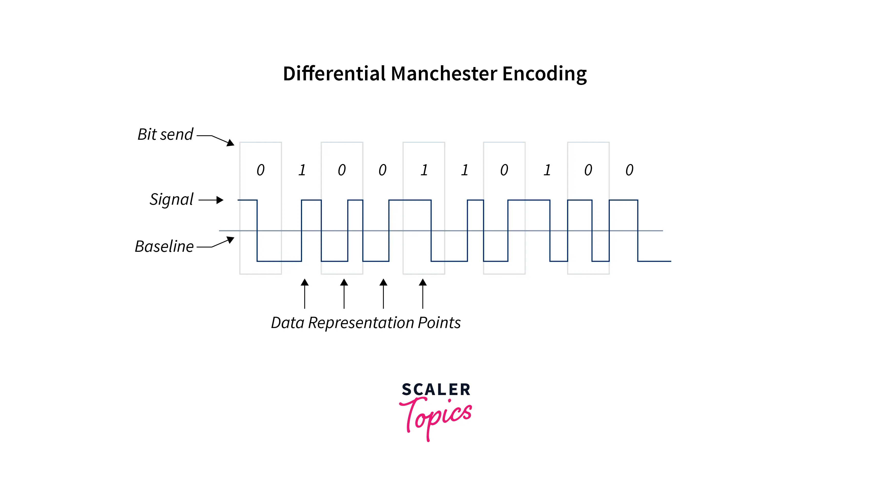
| Each bit period's midpoint contains a transition. | Data representation is mapped in accordance with the bit start time instant and a dedicated mid-bit transition utilised only for clocking. |
| Transition is utilised for both data mapping and clock edges. | A bit period that begins without a transition is represented as 1. |
| High to Low signifies 0 and Low to High represents 1. | The Beginning of a bit period transition is represented as 0 (Inverts on 0's - the opposite of NRZI) |
| Applied to IEEE 802.3 Ethernet LAN specification (Short distances) | Example: The IEEE 802.5 specification for Token Ring LAN uses differential encoding. |
Manchester Encoding
Differential Manchester Encoding
Conclusion
- The receiver can synchronise on the transition that occurs in the middle of each bit period in Manchester encoding. Better synchronisation is consequently achieved.
- The clock signal is extracted by the Digital Phase Locked Loop (DPLL), which then reallocates each bit's value and time. There must be a lot of bit transitions in the transmitted bitstream.
- In Manchester, a bit's duration is split in half. During the first half, the voltage stays constant at one level before switching to another level.
- Now that you're aware of what Manchester encoding is and why it's advantageous, even with the potential data rate reduction and the additional hardware or firmware required to create and decode Manchester-encoded data.
- Manchester code is one of the many different forms of line codes. Its creation is fairly simple and depends on comparing the clock and data signals. This type of encode signal has the advantage of having memory, thus the needed bandwidth is bigger than with other codes. Because of this, it can be used with other networks, including Ethernet.