Spanning Tree Protocol (STP)
Overview
Spanning Tree protocol is a link management protocol. It is used for creating a loop-free network. It is also a layer-2 protocol that runs on bridges and switches. In IEEE standard, it is standardized as IEEE 802.1D.
Introduction
- Spanning Tree Protocol (STP) is a link management protocol. The main work of the spanning tree protocol is to create a loop-free network.
- STP creates this network by observing the network so that it can track all the links in a particular network and also blocks the least redundant link.
- STP was created to provide support to the links in the network that are redundant. These links halt the switching loop in the particular STP network.
What is STP?
STP is a link management protocol and also a layer 2 protocol. STP generally runs on switches and bridges. And these must be required to enable on-switch interfaces. STP is standardized as IEEE 802.1D in IEEE format. Before running the spanning tree, switches must be enabled for STP within the same network. This is done so that the selection of the "root bridge" can be performed accurately. The bridge with the lowest bridge ID is called as root bridge. It is considered a reference point for all the switches connected in a spanning tree topology.
Need for STP
There are some conditions in which STP is necessary. Some of them are given below:
- STP is used when there are loops in a network and the reason for loops is the broadcast storm. In the broadcast storm, there are a huge number of broadcast packets in a network in a very short period of time.
- When redundancy is introduced in the network, the reliability (fault tolerance) in the network increases exponentially in this situation STP is required.
- When a condition occurs that the traffic is required to transmit to a destination especially one that is not yet recognized then the switches flood that traffic out from all ports.
- The Spanning Tree protocol uses a physical topology having loops for designing a loop-free logical topology.
How Does STP Work?
Refer to the below image for the working of STP.
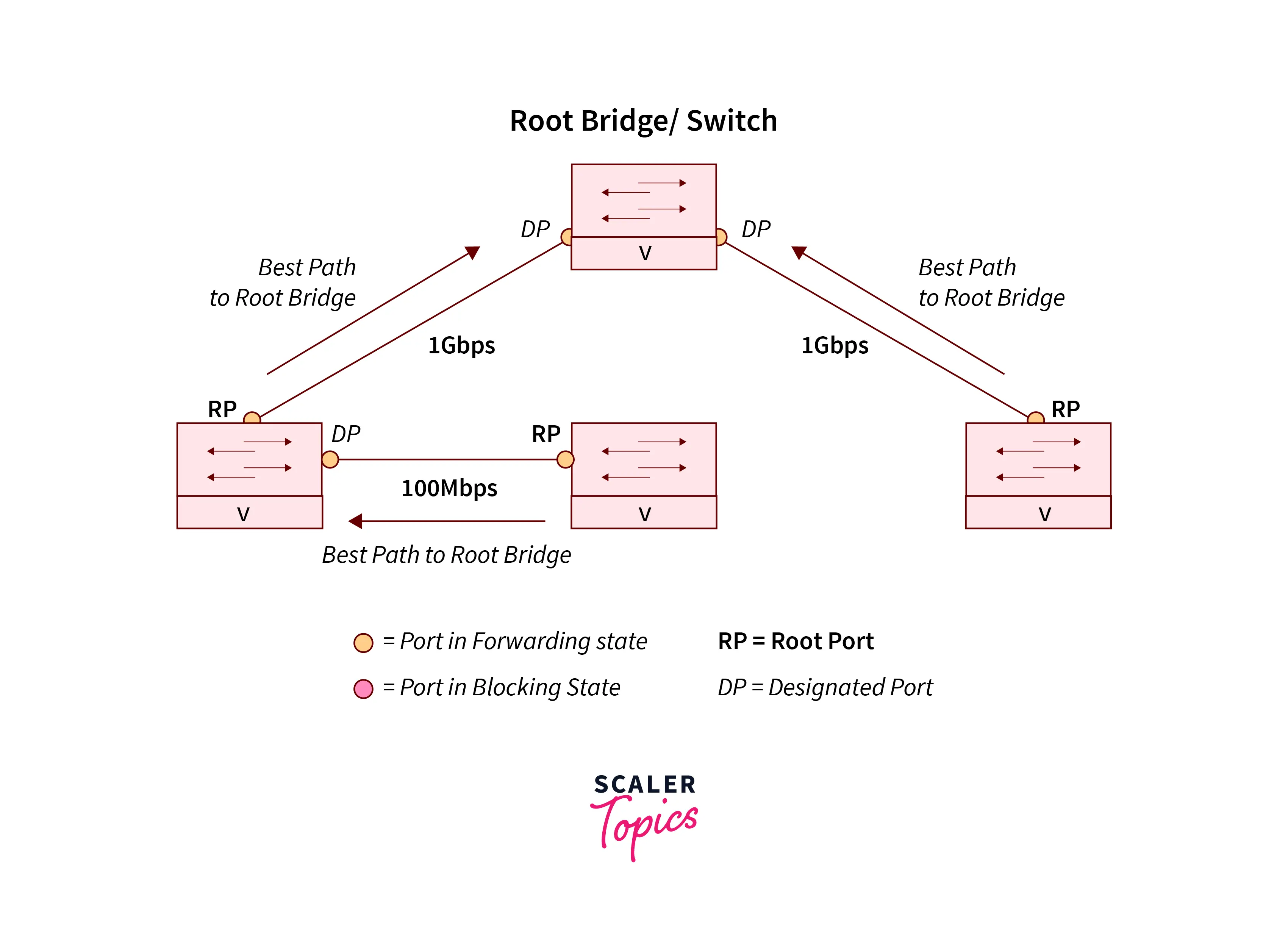
To find the redundant link and the best paths in the LAN network, the scanning tree uses an algorithm. All the links in the network are placed either in a forwarding or blocking state with the help of the spanning tree protocol. After all this procedure, the forwarding state is likely to be considered for all the links that are without redundant links. The Blocking state is considered for all the redundant links that are not so good as compared to selected links. Spanning tree protocol does not use the load-sharing feature. It never allowed multiple links for the same Destination.
Types of STP
| Standard | Description | Abbreviation |
|---|---|---|
| IEEE 802. 1D. | Loop Prevention: In the situation of modification auto-config the tree and provides slow convergence (up to 50 bps) | STP |
| IEEE 802. 1w | Rapid Spanning Tree Protocol: Improvement of STP and provides faster convergence in comparison to loop prevention and also backward compatible with STP | RSTP |
| IEEE 802. 1Q | Virtual LAN: One common spanning tree is defined for all the VLANs. | CST |
| Cisco Proprietary | Per VLAN Spanning Tree: For every VLAN one STP instance and PSVT+ is an improvement over PSVT. | PVRST+ or R-PVST+ |
| Cisco Proprietary | Per VLAN Rapid Spanning Tree | PVRST+ or R-PVST+ |
| IEEE 802.1s | Multiple Spanning Tree protocol: For one STP mapping multiple instances of VLAN | MSTP or Ml STPIEEE 802.1s |
Criteria for Spanning Tree
For determining, that the interface belongs to the forwarding state there are three criteria for spanning the tree:
- It is mandatory to place all the interfaces that are available on the root bridges in a forwarding state.
- Some bridges are not present on the root bridges. So place the nearest port of the root bridge in a forwarding state.
- A designated bridge is a type of bridge that has the lowest admin interval to the root bridge.
Stage of STP Protocol
Following are the stages of Spanning Tree Port:
Refer to the below image to show the stages of STP

Blocking State
Block state is the type of non-designated port. The blocking state is not involved in the frame-forwarding process. The time limit of the blocking state is 20 sec or unlimited. Whenever STP is enabled, the interface always enters into a block state.
Listening State
The first state among all the states is the listening state. It is a type of interface that arrives after a blocking state. It helps you decide whether the interface should be involved in the frame-forwarding process or not. Some functions performed by the listening state:
- Receiving BPDUs
- Discarding the frames that are received on the particular port.
- Not to learn the addresses.
Learning state
A learning state is a type of state that is very helpful in preparing for frame-forwarding process participation. There is an interface that permits us to arrive in the learning state and leave the listening state.
The following functions are performed by the learning state:
- Its function is to receive the BPDUs.
- FRAMES ARE RECEIVED ON THE PORT SO ITS WORK IS TO DISCARD THE FRAMES.
- And also perform the function of learning the addresses.
Forwarding State
A forwarding state is a type of state in which forward frames are created by an interface. These interfaces arrived in the forwarding state from the learning state. After this, accomplish the functions given below:
- Its function is to learn the addresses
- The Function of receiving the BPDUs
- Receiving and forwarding the frames that are received on the particular port.
Disabled State
A type of state that is not involved in the spanning Tree loop is known as a Disabled State. In this state, the port is administratively disabled, and also it has unlimited timing so this state does not participate in the spanning tree loop.
The following functions are performed by the disabled interface:
- On the port, discard the frame that is received.
- BPDUs are not received.
- Addresses are not learned.
Important Terms Used in Spanning Tree Protocol
Some important terms used in the spanning Tree protocol are given below:
Bridge
The important element of STP is the bridge. The bridge is used for connecting two or more LAN segments.
Root Bridge (RB)
A type of bridge that provides points of interconnection for all segments in a network is known as the root bridge.
Non-Root Bridge (NRB)
A type of bridge that is not the root bridge is known as the non-root bridge
Root Port (RP)
A type of port that leads toward the root bridge is known as the Root Port (RP).
Designated Port (DP)
Every LAN segment must have one designated port. DP transfers the frame to each bridge. After this, the bridge passes these frames toward the root bridge through its RP.
Port ID
For the determination of the root port, the port ID is used. Port ID contains a configurable 1-byte priority value and for each bridge, there is a unique code number.
Path Cost (PC)
The other name for path cost is PC. It is used in determining the best topology with respect to speed forwarding. The concept of path cost is used by the STP.
Designated Ports
A Designated Port is a type of port that is usually blocked by a network admin as it is a disabled port. This type of Port is unable to transfer any packet to the other switches. On the MAC table, this is not a populated MAC address.
Non-Designated Ports
A Non-designated port is sometimes also known as a blocked port or an alternative code. As it is a blocked port, it cannot be able to transmit packets to the other switches. In the MAC table also, it does not populate the MAC address.
RSTP
RSTP stands for rapid scanning tree protocol. It is a network-type protocol and it assures a loop-free topology for networks in Ethernet.
Bridge Protocol Data Units (BPDU)
- There is a requirement for an STP network device for the Spanning Tree Protocol for transmitting the message. These messages are generally known as BPDUS ( Bridge Protocol Data Units). BPDUs are sent by each network device for exchanging topology information.
BPDUs allow the switches to do the following:
- Choose a switch that will behave like a root of the spanning tree.
- If no switch is available then choose one of its ports that will act like a root port.
- Ports that are part of the algorithm of the spanning tree are called designated ports these ports are required to be picked up.
- All the non-designated ports are to be blocked.
Differences between STP and RSTP
| STP | RSTP |
|---|---|
| STP stands for Spanning Tree Protocol | RSTP stands for Rapid Spanning Tree Protocol |
| In the STP, BPDU is sent by the bridge only when it reviewed their root protocol(RP) from the root bridge (RB) | RSTP enables the switch to send out BPDU every hello time. |
| STP has two ports - the designated port and the root port. | RSTP has an alternate port, additional port, and backup ports. |
Conclusion
- Spanning Tree protocol is a layer 2 protocol.
- It uses an algorithm for finding the redundant links in the LAN network.
- It is used for creating a loop-free topology.
- Types of STP are Rapid Spanning Tree Protocol, virtual LAN, Per VLAN spanning tree, Per VLAN Rapid spanning tree, Multiple Spanning Tree Protocol, etc.
- Some important terms used in STP are root bridge, non-root bridge, root port, port ID, designated port, etc
- Stages of RSTP are forwarding, blocking, learning, listening, and disabled state.
- RSTP provides loop-free topology in the Ethernet network.